
Enterprise Integration Project Management |
|
|
|
|
PERA provides a proven structure for the management of enterprise programs and projects. This typically involves an initial Master Planning Program to establish policies, objectives, standards, procedures, etc., for both corporate and plant operations. This is then followed by a project implementation phase to execute the projects approved as part of the Master Plan. After projects are implemented, an operations and maintenance phase begins and continues until the enterprise is decommissioned or refurbished.
PERA is a GERAM (a General Enterprise Reference Architecture and Methodolgy) intended for planning, implementing, and operating Enterprise Integration and Business Process Engineering for a corporation.
As such PERA is intented to address all types of enterprise including all architectural levels from field sensors to the board room.
For a full description of the GERAM Framework, its history and current developments see Wikipedia - Generalized Enterprise Reference Architecture and Methodology
PERA Project Management is based upon:
PERA divides the Enterprise Life Cycle into 8 Phases, and each of the Phases from Preliminary Engineering to Decommissioning is divided into People, Facilities, and Systems as indicated in the following diagram.
Note that Operations may be followed by decommissioning and asset disposal, or by maintenance or upgrade projects as is often undertaken during periodic "plant shutdowns"
Good project management requires strong Phasing of project activities
Project deliverables must be well defied and their timing coordinated between Principal and Professional Roles. This is described in the User Guides for that Industry that typically include User Guides for the Owner, EPC, Vendors, and Service Providers.
The Purdue Enterprise Reference Architecture (PERA) is designed to address all industries
Although integration projects have much in common across industries, there are differences that must be understood and accommodated. It was therefore necessary to establish a PERA industry classification system. This classification system is used when defining industry-specific terminology, principal and professional roles, security and safety risks and opportunities for improvement. It may also be cross-referenced to other industry classification systems including SIC, NAICS and US Critical Infrastructure Code.
Principal Roles
In any given industry sector,there are a number of "Principal Roles" that work with the Owner/Operator to achieve the goals of the Enterprise. For a Generic Process Industry Principal Roles might include:
Professional Roles
Within each Principal Role (e.g. Owner/Operator) there are a number of "Professional Roles". Management of Enterprise Integration projects requires expertise from many professional Roles as listed below.
These example Professional Roles are for Enterprise Integration projects in Process Industries, however other types of project in other industries will involve different Professional Roles. A list of relevant Professional Roles is established in PERA User Guides for that industry.
These User Guides are structured as follows:
|- Industry Sector (e.g. Chemical Plant or Automotive)
|--- Prinicipal Role (e.e. Owner/Operator or Vendor)
|----- Lifecycle Phase (e.g. Master Planning or Operations)
The following diagram shows how an Owner/Operator might use a PERA Master Plan to establish standards and practices for use in subsequent projects.
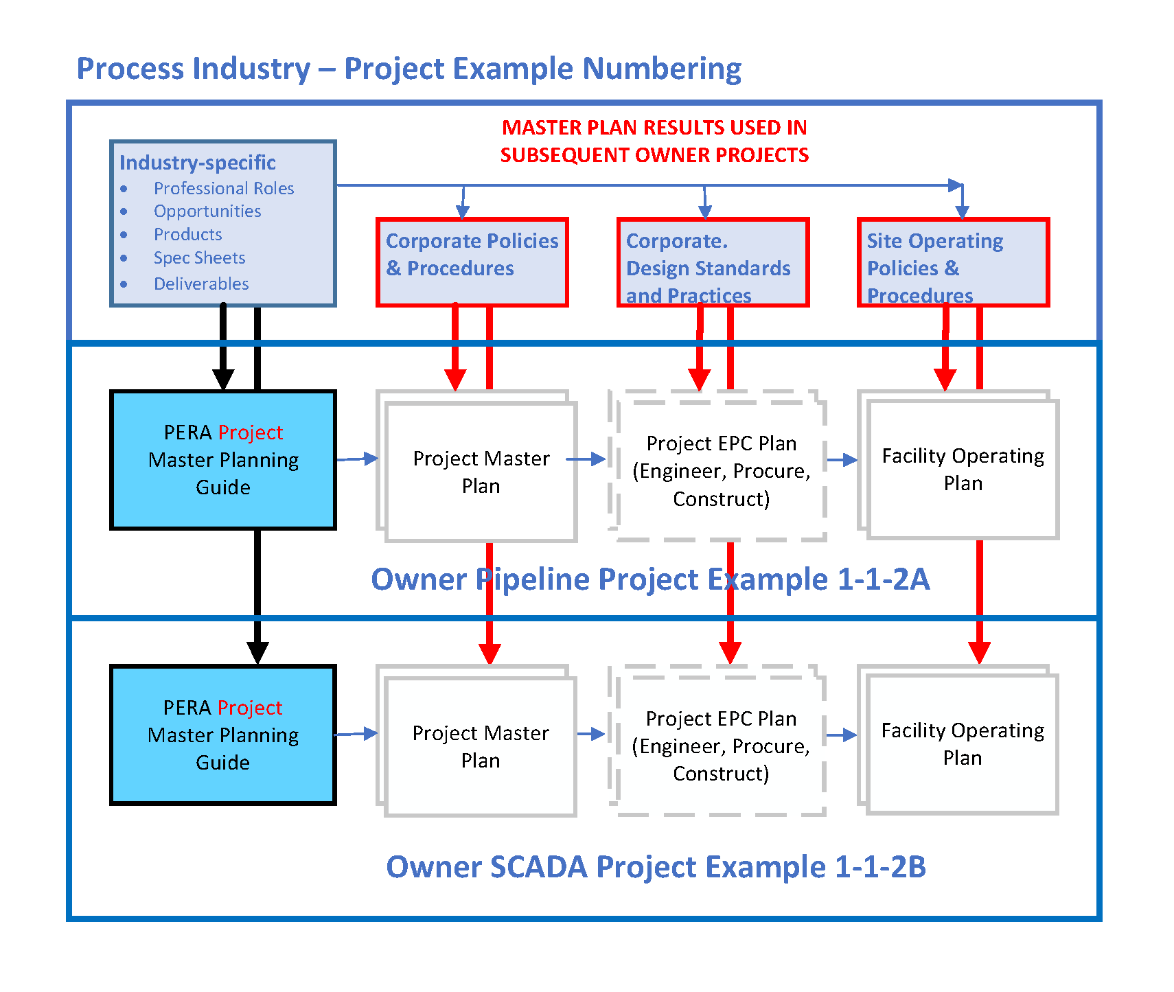
User Gudes may be used to plan and execute projects with or without a Master Planning Phase. For example, repeat projects for a given plant may already have established all required design and operating practices and procedures. In this case the project might proceed directly to Preliminary Engineering. In such cases it may even be possible to compress Preliminary Engineering by reusing design documents and databases; however, this should be done with caution as the cost and schedule impact of changes during Detail Engineering can be devastating.
Note that for large projects the Engineering, Procurement and Construction (EPC) are typically subcontracted by the Owner/Operator to a specialist contractor. EPC is therefore shown as "dashed".
PERA Master Planning may be used for Projects as described above, or for "Programs" such as establishing a process safety program, or a company cybersecurity program. A set of User Guides for a Cybersecurity Program for a process industry enterprise is provided under the "Cybersecurity Topic".
How are PERA concepts used to improve Project Execution ?
PERA Provides an coherent overall Project Strtucture. It begins with Definition
of the Facility, Human Roles (e.g. Engineering Discipline), and Control and Information
Systems.
These are in turn divided by Enterprise Phase.
1) Facility is subdivided by Area/Unit/Equipment Class.
a. Equipment Classes are associated with Disciplines Each equipment class has only one Lead Discipline. The Lead Discipline defines and manages the Specification. Specifications can be for Human Roles, Systems, or Equipment. The line of automation establishes the balance between these 3 (which is defined during Preliminary Engineering).
b. For each Facility Equipment type there may (or may not) be a narrative specification (during Conceptual Engineering), a Specification Sheet (during Preliminary Engineering and each subsequent Phase).
c. Each equipment type has a “Level” in the Enterprise Architecture (although a few can have more than one).
2) Human Roles are broken down into Work Processes, Work Flow Diagrams, Tasks, etc.
a. ISA 108 has defined a standardized breakdown for use in preparing their standards (using BPMN 2). It may be as good as any, or you may know a more authoritative one.
b. For each Position Description there should be a definition of which Roles are assigned to that Position.
c. Roles are defined by one Lead Discipline, but may be assigned to a person in any Position who has the necessary skills and certifications.
3) Control and Information Systems are broken down into Hardware and Software.
Software is sub-divided into programs, subroutines, databases, data dictionaries, etc..
a. Again there are standard terminologies and conventions. (see PERA Dictionary and FAQs)
b. ISA 95 has defined some standard Industrial Systems, as well as Architectural Levels where these reside.Computer and Network Hardware is classified as Equipment (see “1” above)
Schematic Diagrams
All of the above may be associated using “schematic” diagrams that are produced at increasing levels of detail during each successive Phase. For example:
1) Facilities
a. Conceptual Engrg: PFD (Process Flow Diagram)
b. Preliminary Engrg: P&ID (Piping and Instrumentation Diagram)
c. Detail Engrg: Piping Isometrics, Installation Details
d. Construction: Shop Fabrication Drawings (e.g. spool piece drawings, weld diagrams, stress drawings)
2) Human Roles
a. Conceptual: Organization Charts
b. Preliminary: High Level BPMN “swim lane” Diagrams
c. Detail: Work Flow Diagrams
d. Implementation: BPMN 2 “executable” Diagrams (with BPM system)
3) Systems
a. Conceptual Engrg: Enterprise Systems Architecture Diagrams
b. Preliminary Engrg: CIAD (Control & Information System Architecture Diagrams)
c. Detail Engrg: Loop Diagrams, DCS and PLC configurations
d. Construction: Operator Display Graphics, Trend Displays
The above is not meant to be an exhaustive set, but gives an indication of the
kinds of Schematic Diagrams that may be used to show how Facilities, People
and Systems are related.
PERA User Guides, MLMS and discussion white papers are provided that provide much more detail for each of the Professional Roles involved in Enteprise Integration projects. (see PERA Courses topic).